Sankey diagram (Alluvial Diagram)
What’s this?
Macro for Sankey diagram using SAS GRAPH.
To be more precise, it is called alluvial Diagram.
A Sankey diagram is a visualization used to depict a flow from one domain of values to another domain. Sankey graphs is useful for showing flow and relationships among multiple categories.
In pharmacoepidemiology study, this diagram is used for changes of the state of a patient over time, such as medication switching, disease stage progression, or movement through treatment pathways. 1.
In the past, there are reports of sankey diagram example using SAS GRAPH 23. But in this macro, more options such as statistics display and node focus are available.
If you can allow the use of HTML, I suggest you refer to the case study of using D3.js and SAS 4.
Elements of Sankey diagram
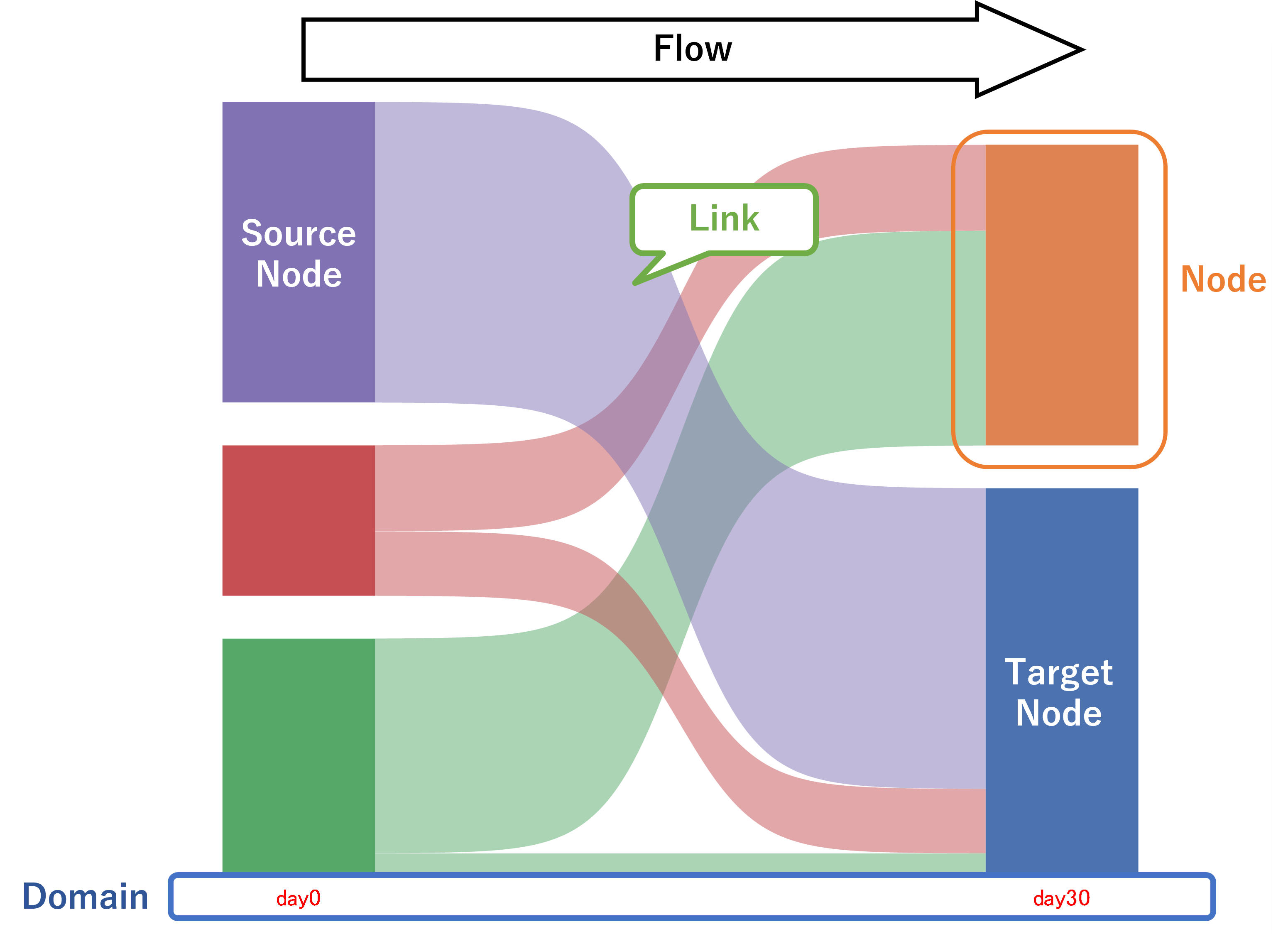
Sankey diagram is contained the three elements.

domain
the group of data as x-axis
Node
the category. displays as rectangle shape.
link (flow)
sigmoid shapes connected from node (source node) to next node (target node). amounts of flow are displays as widths of sigmoid shapes. the links connect the nodes in order left domain to right domain.
Rules
the nodes are stacked in node category order.
all records of the input data are displayed in the all domains.
nodes in the first domain should be source node only, not target node.
the nodes of last domain should be target node only, not source node.
Circular links are not allowed.
Input data
the node categories are set to each domain variables like below. I recommended that the node category format is applied to each domain variable. the domain variables should be numeric.
null value is allowed. null value is defined as null node and same as other nodes.
domain1 |
domain2 |
domain3 |
node A |
node B |
node C |
node B |
node A |
node C |
node D |
node A |
node B |
the domain format is required.
code
proc format;
  value domainfmt
  1="Domain 1"
  2="Domain 2"
  3="Domain 3"
;
run;
Syntax
 ods graphics / < graphics option > ;
 ods listing gpath=< output path >;

%macro sankey(
   data=,

   domain=,
   domainfmt=,
   domaintextattrs=(color=black size=11),
   gap=5,

   nodefmt=auto,
   nodewidth=0.2,
   nodeattrs=auto,
   nodename=true,
   nodetextattrs=(color=black size=9),

   linktext=true,
   linktext_offset=0.05,
   linkattrs=auto,
   linktextattrs=(color=black size=8),

   reverse=false,
   focus=None,
   endFollowup=None,
   stat=both,
   unit=,

   legend=false,
   palette=sns,
   note=,
   deletedata=true);
Parameters
data : dataset name (required)
input data. keep and rename options are available but keep option is not. input data is copied to work library and keep only domain variable set to domain parameter.
Domain settings
domain : variable name (required)
domain variable. domain variables are set in link order. for example, if domain parameter is set as “var1 var2 var3”, the var1 and var2, var2 and var3 are connected.
domainfmt : variable name (required)
format for domain variable. format catalog should be saved in work library and value should be numeric. interval of domains is depends on the values of format. labels of the format are displayed on plot. values not be included into sankey should be exclude from format.
domaintextattrs : text appearance (optional)
The appearance (font size, font color and font weights) of domain text. it is same as textattrs of GTL. default is “(size=11 color=black).
Node settings
gap : numeric (optional)
the gap between nodes. default is 5.
nodefmt : keyword or format name (optional)
format for nodes. if “auto” is set, format is obtained from domain variable in input data. if you want to display the node which is not existed in input data in the legend. the node format should be set to this parameter. format catalog should be saved in work library. default is “auto”.
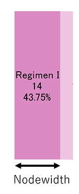
nodewidth : numeric (optional)
the width of node shapes. the default is 0.2.

nodeattrs : keyword or fill appearance (optional)
node appearance (color, transparency). it is same as fillattrs option of GTL. if “auto” is set, the fill color of nodes are set based on the node category. if you want to be set same color to all the nodes.fill attribute is set to this parameter.
for example, the fill appearance described below is set and the all nodes is set blue.
nodeattrs=(color=blue)
default is “auto”.
- nodename : bool (optional)
displays the node name (node category name) in the sankey diagram. default is “true”.
nodetextattrs : text appearance (optional)
The node text appearance (font size, font color and font weights). It is same as textattrs option of GTL. default is “(size=9 color=black).
Link settings
linkattrs : fill appearance (optional)
fill appearance of link shapes (color, transparency). it is same as fillattrs option of GTL. if the fill appearance is set to this parameter, all the links will be applied. default is “auto”. fill color is defined as source node type.
linktext : bool (optional)
display the link text (frequency or percentage). the text will be displays at the source node side of the links.default is “true”.
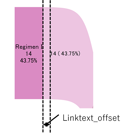
linktext_offset : numeric (optional)
the gap between node shape and link text. default is 0.15.

linktextattrs : text appearance (optional)
the appearance (font size, font color and font weights) of link text. It is same as textattrs option of GTL. default is “(size=8 color=black).
Other settings
reverse : bool (optional)
if True the y-axis will be reversed. default is False.
focus : subset-if statement (optional)
specify the focused links. The links except for focused links will be set grey color and link text will be not displayed. The focused links are specified by nodes connected by focused links using subset if statement. variables that can be used for subset if are as follows.
domain: domain of source_node
next_domain: domain of target_node
source_node: source node of focused link
target_node: target node of focused link
for example, when links connected from “type A” node (source node) of domain 2 is focused, set the parameter described below. value of type A node is 1.
focus=(source_node=1 and domain=2)
default is “none” (not focused).
EndFollowup : node (optional)
specify the node of end of follow-up. The color of node specified this parameter will be set grey and the percentage of follow-up at each domain will be displayed at the bottom of Sankey diagram. default is “none” (not specified).
the percentage of follow-up is calculated using following equation.
%follow-up = (total number - number of EndFollowup) / Total number * 100
stat : keyword (optional)
displays the frequency or percentage of nodes and links. the keyword described below is available. default is “both”.
FREQ: frequency
PCT: percentage(displays second decimal place)
BOTH: frequency and percentage
NONE: not displayed
the percentage is calculated using following equation.
percentage = frequency of nodes or links / number observation of input data * 100
unit : text (optional)
the units of frequency (suffix). if “FREQ” or “BOTH” keyword is set to the stat parameter, the units of frequency is displayed in the node text and link text.
default is “” (null).
legend : bool (optional)
if “True” the legend of node category item is displayed. default is “false”.
palette : keyword (optional)
color palette for fill, line and markers. the palettes described below is available. see color palette section of introduction page. default is “SNS” (Seaborn default palette).
SAS
SNS (Seaborn)
STATA
TABLEAU
note : statement (optional)
insert the text entry statement into the graph template and display the title or footnote in the output image. default is “” (not displayed)
- deletedata : bool (optional)
if True, the temporary datasets and catalogs generated by macros will be deleted at the end of execution. default is True.
example
output example can be executed using following code after loading SAS plotter.
code
ods listing gpath="your output path";
filename exam url "https://github.com/Superman-jp/SAS_Plotter/raw/main/example/sankey_example.sas" encoding='UTF-8';
%include exam;
Basic sankey diagram
the regimen changes of the patients is displayed as sankey diagram using this macro. variables (day0, day30, day60, day120) are selected regimen of the patient at 0 ,30, 60 and 120days. these variables is set the regimen types.
raw data
proc format;
value domainf
1="day0"
2="day30"
3="day60"
4="day120";

value nodef
0="Drug A"
1="Drug B"
2="Drug C"
3="Drug D"
4="Drug E"
;
run;
data raw;
usubjid+1;
input day0 day30 day60 day120;
format day0 day30 day60 day120 nodef.;
cards;
0 2 3 4
0 2 3 4
0 2 3 4
2 1 2 4
2 1 2 4
2 1 2 4
2 1 2 4
2 1 2 4
2 1 4 3
4 3 2 1
4 3 2 1
4 3 2 1
4 3 2 1
;
run;
code
ods graphics / height=15cm width=20cm imagefmt=png imagename="sankey_basic" noborder;
title "Bacic Sankey";

%sankey(
   data=raw,
   domain=day0 day30 day60 day120,
   domainfmt=domainf,
   note=%nrstr(entrytitle 'your title here';
            entryfootnote halign=left 'your footnote here';
            entryfootnote halign=left 'your footnote here 2';)
   );
Adjust the domain interval
The interval of the domain is defined as the values of the domain format. when the domain format values are adjusted, then interval of the domain will be changed.
if the format is changed described below, the plot of the previous section “basic sankey diagram” is as follows.
code
proc format;
value domain2f
1="day0"
2="day30"
3="day60"
5="day120";
run;

ods graphics / height=15cm width=20cm imagefmt=png imagename="sankey_change_intervals" noborder;
title "Adjust the domain interval";
ods html;
%sankey(
   data=raw,
   domain=day0 day30 day60 day120,
   domainfmt=domain2f
);
Node format and legend
If the codes of the previous section “basic sankey diagram” is changed as described below, the color of the “Regimen E”, “Regimen G” and “Regimen I” is different from the previous section.
By default, the color of the nodes is defined based on the input data and domain variables. when the input dataset is modified, the color of the nodes might be changed even though same node.
code
proc format;
value domain3f
1="day0"
2="day60"
;
run;
ods graphics / height=15cm width=20cm imagefmt=png imagename="sankey_not_set_nodefmt" noborder;
title "not set nodefmt parameter";

%sankey(
   data=raw,
   domain=day0 day60,
   domainfmt=domain3f,
   legend=true
);
if nodefmt parameter is set, the color of the nodes defined based on the node format. The node color is independent from dataset. All elements of the format is displayed in the legend if legend parameter is true.
code
ods graphics / height=15cm width=20cm imagefmt=png imagename="sankey_set_nodefmt" noborder;
title "set nodefmt parameter";

%sankey(
   data=raw,
   domain=day0 day60,
   domainfmt=domain3f,
   nodefmt=nodef,
   legend=true
);
Change the fill appearance
By default, the node color and the link color are defined based on the node category. If the nodeattrs or linkattrs are set, the fill color of the all the nodes or links will be changed. Nodefmt parameter will be ignored.
code
ods graphics / height=15cm width=20cm imagefmt=png imagename="sankey_set_nodeattrs" noborder;
title "change_the_node color";
ods html;
%sankey(
   data=raw,
   domain=day0 day30 day60 day120,
   domainfmt=domainf,
   nodeattrs=(color=grey)
);
code
ods graphics / height=15cm width=20cm imagefmt=png imagename="sankey_set_linkattrs" noborder;
title "change the link color";
ods html;
%sankey(
   data=raw,
   domain=day0 day30 day60 day120,
   domainfmt=domainf,
   linkattrs=(color=skyblue transparency=0.7)
);
Change the text appearance
The domaintextattrs, nodetextattrs and linktextattrs parameters are useful for modify text appearance of domains, nodes and links.
code
ods graphics / height=15cm width=20cm imagefmt=png imagename="sankey_set_textattrs" noborder;
title "change the text appearance";
ods html;
%sankey(
   data=raw,
   domain=day0 day30 day60 day120,
   domainfmt=domainf,
   domaintextattrs=(color=red size=12),
   nodetextattrs=(color=blue size=12),
   linktext_offset=0.05,
   linktextattrs=(color=green size=8)
);
Focus parameter
The focus parameter is useful for the highlighting specified links. The not-highlighted links are set grey color and the link texts are not displayed.
focus links are specified by nodes connected by focus links and the nodes is specified conditional statement (subset-if).
the nodes described below are available to specify the focus links.
raw data
proc format;

value druglist
1="Drug A"
2="Drug B"
3="Drug C"
4="Drug D"
99="Lost to follow-up";

value timef
1="Day 0"
2="Day 30"
3="Day 60"
4="day 90"
;
run;

data drug_switch;
length usubjid $10 Day0 Day30 Day60 Day90 8;
format Day0 Day30 Day60 Day90 druglist.;
input usubjid $ Day0 Day30 Day60 Day90;
datalines;
A001 1 1 1 3
A002 1 1 1 4
A003 1 1 1 4
A004 1 1 1 4
A005 1 2 1 4
A006 1 3 1 4
A007 1 3 1 4
A008 1 4 1 99
A009 1 4 1 99
A010 1 1 2 2
A011 1 1 2 3
A012 1 1 2 3
A013 1 1 2 3
A014 1 2 2 4
A015 1 2 2 4
A016 1 3 2 4
A017 1 1 3 1
A018 1 1 3 2
A019 1 2 3 4
A020 1 2 3 4
A021 1 2 3 4
A022 1 3 3 4
A023 1 3 3 99
A024 2 4 2 4
A025 2 1 3 3
A026 2 1 3 3
A027 2 1 4 1
A028 2 1 4 2
A029 2 2 4 3
A030 2 2 4 4
A031 2 2 4 4
A032 2 3 4 4
A033 2 3 4 4
A034 2 99 99 99
A035 2 99 99 99
A036 3 1 4 2
A037 3 2 4 4
A038 3 3 4 99
A039 3 1 99 99
A040 3 1 99 99
A041 3 99 99 99
A042 4 4 3 99
A043 4 1 99 99
A044 4 2 99 99
;
run;
example 1: links whose source_node is 1 (Drug A)
code
ods graphics / height=15cm width=20cm imagefmt=png imagename="sankey_focus1" noborder;
title "focus parameter example 1";
%sankey(
   data=drug_switch,
   domain=day0 day30 day60 day90,
   domainfmt=timef,
   focus=(source_node=1),
   gap=1,
   reverse=true,
   nodewidth=0.1,
   nodename=false,
   stat=freq,
   legend=true,
   linktext_offset=0.03,
   palette=sns
);
example 2: links whose target_node is 5 (Lost to followup)
code
ods graphics / height=15cm width=20cm imagefmt=png imagename="sankey_focus2" noborder;
title "focus parameter example 2";
%sankey(
   data=drug_switch,
   domain=day0 day30 day60 day90,
   domainfmt=timef,
   focus=(target_node=99),
   gap=1,
   reverse=true,
   nodewidth=0.1,
   nodename=false,
   stat=freq,
   legend=true,
   linktext_offset=0.03,
   palette=sns);
example 3: links whose domain is 2 (Day 30)
code
ods graphics / height=15cm width=20cm imagefmt=png imagename="sankey_focus3" noborder;
title "focus parameter example 3";

%sankey(
   data=drug_switch,
   domain=day0 day30 day60 day90,
   domainfmt=timef,
   focus=(domain=2),
   gap=1,
   reverse=true,
   nodewidth=0.1,
   nodename=false,
   stat=freq,
   legend=true,
   linktext_offset=0.03,
   palette=sns);
example 4: multiple condition
code
ods graphics / height=15cm width=20cm imagefmt=png imagename="sankey_focus4" noborder;
title "focus parameter example 4";
%sankey(
   data=drug_switch,
   domain=day0 day30 day60 day90,
   domainfmt=timef,
   focus=((domain=1 and source_node=2) or (next_domain=4 and target_node=99)),
   gap=1,
   reverse=true,
   nodewidth=0.1,
   nodename=false,
   stat=freq,
   legend=true,
   linktext_offset=0.03,
   palette=sns);
Percentage of Followup
when the endfollowup parameter is set value of lost followup, percentage followup each domain will be displayed below the sankey diagram.
code
ods graphics / height=15cm width=20cm imagefmt=png imagename="sankey_endfollowup" noborder;
title "percentage of Followup";
%sankey(
   data=drug_switch,
   domain=day0 day30 day60 day90,
   domainfmt=timef,
   gap=1,
   reverse=true,
   nodewidth=0.1,
   nodename=false,
   endfollowup=99,
   stat=freq,
   legend=true,

   note=%nrstr(entrytitle 'your title here';
               entryfootnote halign=left 'your footnote here';
            entryfootnote halign=left 'your footnote here 2';)
);
Reference
- 1
Nicolle M. Gatto, Shirley V. Wang, William Murk, Pattra Mattox, M. Alan Brookhart, Andrew Bate, Sebastian Schneeweiss, and Jeremy A. Rassen. Visualizations throughout pharmacoepidemiology study planning, implementation, and reporting. Pharmacoepidemiology and Drug Safety, 31(11):1140–1152, 2022. URL: https://onlinelibrary.wiley.com/doi/abs/10.1002/pds.5529, arXiv:https://onlinelibrary.wiley.com/doi/pdf/10.1002/pds.5529, doi:https://doi.org/10.1002/pds.5529.
- 2
Chapel Hill Shane Rosanbalm. Getting sankey with bar charts. 2015. URL: https://www.pharmasug.org/proceedings/2015/DV/PharmaSUG-2015-DV07.pdf.
- 3
Sanjay Matange. Sankey diagrams. 2015. URL: https://blogs.sas.com/content/graphicallyspeaking/2015/03/21/sankey-diagrams/.
- 4
Tanmay Khole. Using sankey diagram to analyze drug pipeline. 2020. URL: https://www.lexjansen.com/phuse-us/2020/dv/DV03.pdf.